Showing posts with label G0704. Show all posts

Monday, September 1, 2014

Hydraulic Power Drawbar

The power drawbar design I used came from the Hoss CNC plans (PDB v2). It puts no force on the spindle bearings and took me quite a while to understand how it works (clamping the tophat). I originally planned on using a 4" 3 stage pnuematic cylinder like everyone else does but after I decided the 56c motor was going on the mill head I just didn't have room for such a large cylinder.

I decided to go with air over hydraulic. I looked at building my own air over hydraulic booster but it was much easier to buy one off ebay. I got an Enerpac B3006 booster along with a CST-40251 threaded hydraulic cylinder. The cylinder is about 2 inches wide and the exterior body is threaded 1.875-16 UNC. All you have to do is make a giant threaded hole in your PDB mounting bracket and it fits great. This is a great opportunity to do thread milling with a single point tool on your mill if you haven't already.

I was concerned about TTS tool pullout and with the B3006 booster I can produce about 3000psi in the hydraulic fluid. The CST-40251 cylinder has a surface area of 1.76 square inches so I can produce about 5200 lbs of force. The standard 4" 3 stage pneumatic cylinders produce about 3600 lbs. Tormach recommends 2500lbs of force on the drawbar to keep tools from pulling out.

The first time I activated the PDB I forgot about the 1.76 multiplier and actually bent the steel lifting plate with 4000 lbs of force. I plan on reinforcing the lifting plate and top plate by adding a vertical support that spans to front (ie a load bearing beam). It will be held on with two bolts so you can remove it and tighten or loosen the drawbar nut.

I did change the plans for the PDB slightly. I had to make it wider so it would fit my wider motor mounts and made more room between the lifting plate and the top plate. That extra room allows me to add more bellville washers for more force.

I would like to release the hydraulic PDB plans on Grabcad but since they were originally Hoss's design I'll need to ask him first. If you have the original Hoss plans and my Grabcad model of the 56c motor mount It will be pretty obvious how to make it slightly wider and taller to fit your situation.

Lifting plate. I made the slot slightly wider

Lifting plate with legs on base

Testing single point threadmilling for cylinder fit

Completed Hydraulic PDB


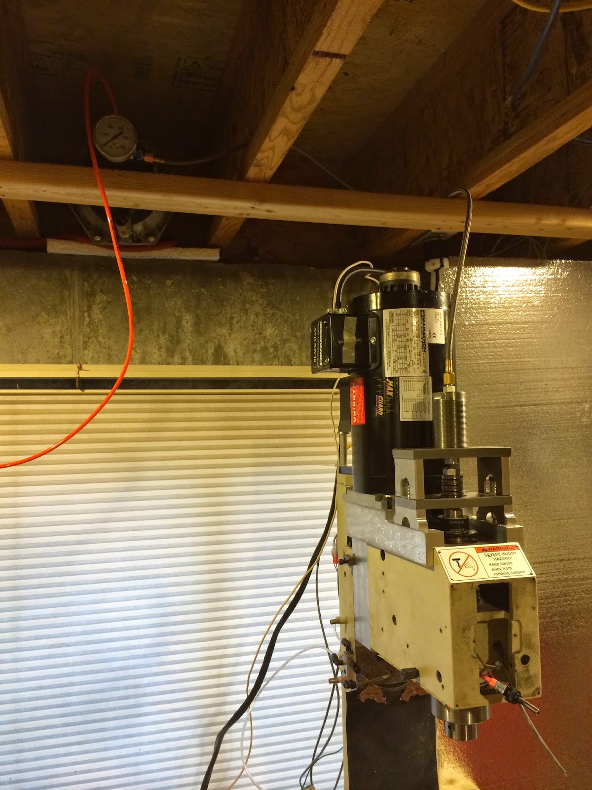
Completed PDB on mill


You can see the Enerpac B3006 in the rafters on the left

If you make a PDB you absolutely need a lockout on it so you don't activate it while the spindle is running. I know, you're the careful type who would never do that, but things happen and you will destroy your mill if the PDB activates while the spindle is going 5k rpm. Good news is, it's pretty easy to do. The concept is to take some output from the VFD that triggers when it's at zero speed and using a relay tie that to the PDB activation switch.

In my setup I use a 24v SPDT relay to take terminal B3 from my VFD and use that to determine whether the 12v+ line on the PDB switch should have power. If the terminal is high (ie spindle is stopped) then the PDB switch has power and can work. If the terminal is low, power is cut to the switch and you can flip it all you want and nothing will happen.

24v relay documentation


I have the switch for the PDB mounted on my mill head. If you wanted it to be controlled from LinuxCNC it would be very simple. Someday I might build an automatic tool changer and then I would need the PDB to be operated by LinuxCNC.


Tuesday, August 26, 2014

Limit Switches

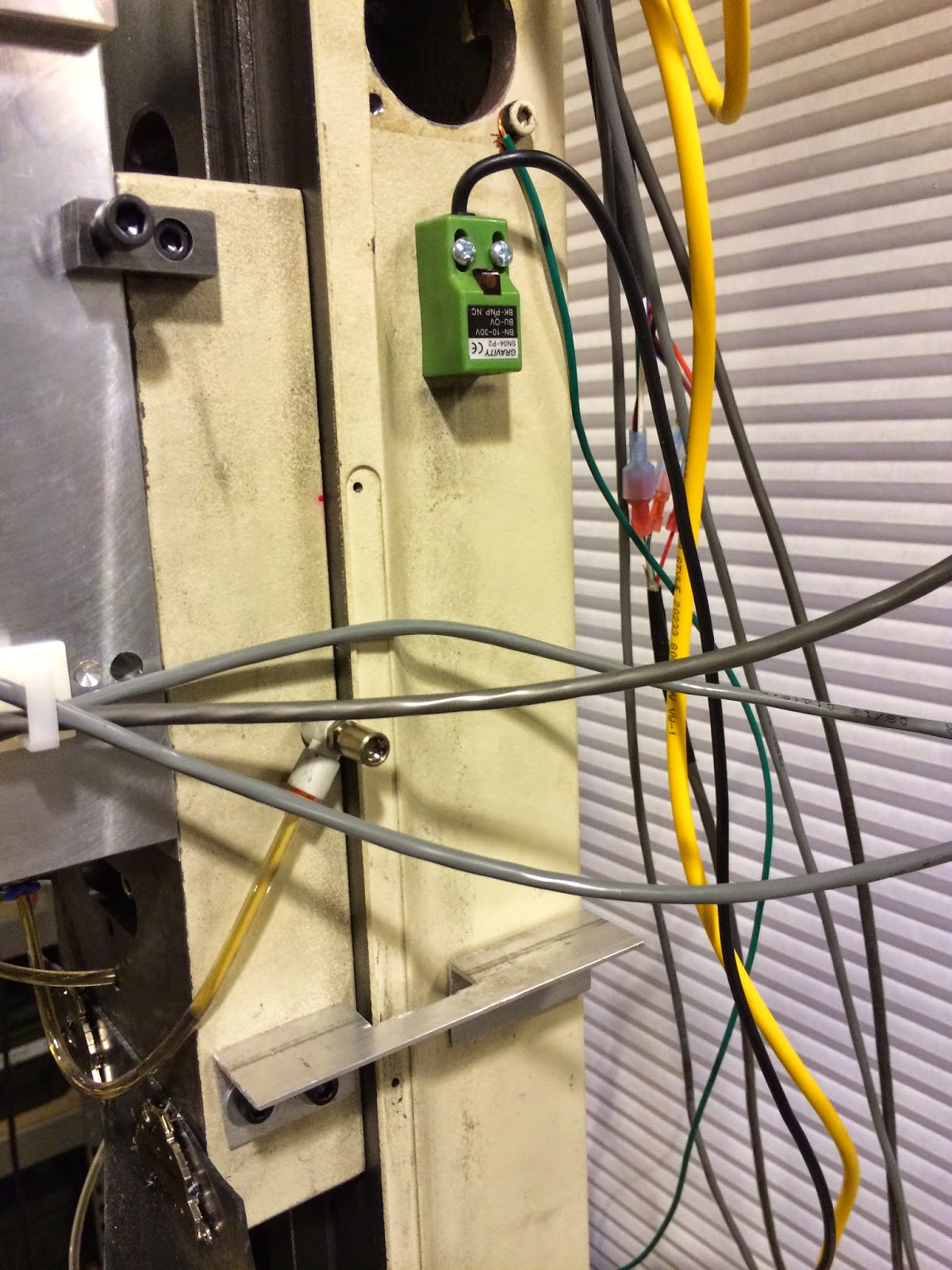
I chose to use proximity switches off ebay (SN04-P2 DC 3-Wire PNP NC 5mm Detecting Distance Proximity Switch 10-30V). They were about $7 each shipped and mine had green square ends. They make all different varieties but if you're using Mesa hardware you want the PNP versions rather than NPN. Hook one switch wire to the 12v power supply and the signal line to the Mesa input pin. Connect ground to ground.

You have to be creative to get the limit switches mounted. All proximity switches sense metal and ideally for maximum repeatability the metal should move perpendicular to the end of the switch. The switches are incredibly accurate. The machine homes to within .0005 every time. Having the limit switches makes starting the machine significantly easier. They were some of the last things I put on but hitting "Home All" and watching the machine home is worth it. It also is pretty much mandatory for using the auto z touch off switch because you have to program in the correct location of the switch which is much easier if the machine home location is always the same.

In LinuxCNC you can control the homing sequence such that the axes will home simultaneously or in the sequence you want. In my case I chose to home the Z axis first, then the x/y axes simultaneously. This avoids any problems with crashing the mill head into the vise or anything else on the table.

You control the homing sequence in NAME.ini under each of the axes. You'll want to add HOME_SEQUENCE=. To control the direction it will home in (ie Z homes towards the top, you set the HOME_SEARCH_VEL positive or negative. Here's how I do Z first and then X/Y together

----------------------------------------------
## X axis
[AXIS_0]
.....
HOME_SEQUENCE=1
HOME_OFFSET = 0.000000
HOME_SEARCH_VEL = -1.0000
HOME_LATCH_VEL = -0.016667
HOME_FINAL_VEL = 0.000000
HOME_USE_INDEX = NO
HOME_IGNORE_LIMITS = YES

[AXIS_1]
.....
HOME_SEQUENCE=1

## Z axis
[AXIS_2]
.....
HOME_SEARCH_VEL = 1.0000
HOME_LATCH_VEL = 0.016667
HOME_FINAL_VEL = 0.000000
HOME_USE_INDEX = NO
HOME_IGNORE_LIMITS = YES
HOME_SEQUENCE=0

---------------------------------------------


I built these x axis end stops that attach to the stock mounting bracket on the end of the mill. You just buy a longer M6x1 bolt from Home Depot and bolt these on. You can adjust the depth they trigger at with the hex head bolt and then put a nut on the other end to lock the adjustment down.


For the Z axis I drilled and tapped the column and then drilled and tapped the z axis saddle for a mount made of angle aluminum. 


For the Y axis I drilled and tapped the base and mounted the two switches on the base. I used the existing holes in the saddle (M6x1) to add that piece of aluminum bar stock. I put tapped holes every 1/2" on the bottom so I could change where the bolt went and adjust the trigger point of the switch


For the X axis I added the switches on the bottom of a piece of angle aluminum. This protects them from swarf


One Shot Oiling


The concept is great, automated oiling. Getting it all to work though is very time consuming. I used 5/32" (4mm) clear tubing off of ebay. The clear tubing is great because you can verify the oil is moving. I also used quick attach pnuematic fittings that were meter in, this is important because they only meter the flow in one direction, in the other direction they are unrestricted. I wish they were check valves instead of being unrestricted. Mostly I used 4mm tubing to 10-32 thread fittings. I am not 100% pleased with the system. Despite buying two check valves the oil will still drain from the z axis overnight.

I also had to track down some long elbow connectors and M6 connectors to get oil in the ballnuts. I had some grinding and drilling/tapping to do on the saddle and base. I would recommend a one shot oiler but I'm not sure I would reuse the same components. I use the system now by manually shutting the two main distribution valves and only opening them at the beginning of a work session when I activate the oiler and move the table around to distribute the oil.

It certainly works, it just doesn't work as well as I had planned.

Oiling grooves on saddle

Oiling manifold and cutouts for ballnut oiling connectors on saddle


Front view of oiling, green things are proximity switches


back view of oiling manifold


One shot oiler pump off ebay

Main distribution manifold - One goes to z axis other goes to x/y


Spindle Motor

The mill comes with a DC brushed motor with a 1HP rating. I feel that is generous because I stalled the motor a couple of times and blew a fuse once. It is certainly capable of cutting metal though. I wanted to replace the motor to gain higher rpms since it maxes out at 2250. I wanted 10k rpm for my spindle, I wanted it controllable from software and I wanted rigid tapping.

I considered 3 options. A large servo motor, a brushless DC motor, VFD with 3 phase motor. I really wanted to find a large servo motor or brushless DC motor that was thin and tall so it would have a similar footprint to the stock motor. I couldn't find one cheaply enough or the right size. There was also very little documentation for controlling some of these motors and the servo drives were expensive too. The reason I didn't want to do the VFD motor is because there are no small 3 phase motors. Most are 56c sized which is frankly pretty massive on the mill. In the end, due to some great ebay deals I bought a 1.5HP 56c motor and a 2HP Emerson Commander SK Vectorless VFD.

There are some large benefits to a Vectorless VFD. They are all designed to take 0-10v speed inputs, have inputs for forward/reverse and most have modbus control so you can fully control them from software. They can deliver all their torque at very low rpms and are almost as cheap as a standard VFD. You don't need any encoder feedback to the VFD. I chose the Commander SK because Tormach picked it for their mills and I got a great deal on one on ebay. I did have to run a 240v circuit to my mill but I have a subpanel in my basement and it was quite easy. I put a heavy duty 240v switch in front of the VFD so I can turn it off when I'm not using it rather than having to flip the breaker.

The motor is a Marathon Blackmax Model Y538. Again, I found a screaming deal on ebay for it. I also would have bought a Marathon MicroMax motor. The Blackmax is an 1800rpm 1.5HP totally enclosed non vented motor that delivers 1000:1 constant torque and is class F rated which means it can be used with VFD's. It has no fan and can technically deliver all it's torque at 2 rpm. It also has a max mechanical speed of 5400rpm. I wanted to go with a 2HP motor but above 1.5HP they only have cast iron frame motors and those weigh 75 lbs or more, I set a limit of 50 lbs of weight because the z axis motor needs to move all this weight up and down.

I hooked up the motor to the spindle using a belt drive based heavily on a fellow named CodeRage. In order to fit a 56c motor and still have a power drawbar you must do the y axis mods and have a head spacer. I made the biggest head spacer that Hoss had plans for (it looks like a tombstone). My belt drive conversion is like all the others. You have a set of mounting plates that sit on the mill head and have a raised section for the motor to mount and a lower section that you'll put the power drawbar assembly on. To fit a 56c motor your mounts will hang off the side of the millhead and extend back past the millhead onto the head spacer.


Belt Drive mill head mounts with motor and mount in back


I used GT2 5mm profile belts in a 15mm height. The GT2 profile is a timing belt profile designed for less noise and higher speeds than the standard trapezoidal (L) profile. I bought aluminum pulleys and a belt from sdp-si.com and made heavy use of their pulley center distance calculator. Due to my desire for a 10k rpm spindle speed and the 1000:1 constant torque VFD and motor, I decided to run a 1:2 pulley ratio.

I used 24 and 48 tooth pulleys (6A55-024DF1512 and 6A55-048NF1516) with a 92 tooth belt which was perfect for my 5.44 inch center distance between the motor and the spindle. The smaller pulley goes on the spindle and the larger pulley on the motor.

The smaller 24 tooth pulley is the perfect size for the G0704. Mill off the hub so you have just a pulley. Bore it out to .851 so it will fit over the splined spindle shaft on the G0704 and then bore out a 1" wide hole recessed .10-15 deep in the top so you can have more threads to secure the drawbar tophat to. This also clamps the pulley between the rpm sensor disc on the bottom and the tophat on the top. To secure the pulley to the splined shaft I drilled 3 holes near the bottom of the pulley, 120 degrees apart in the teeth of the pulley. I threaded them 10-32 and used 1/4" set screws. This leaves the head of the setscrew below the tooth of the pulley which is important since the belt is going to cover the holes.

To use the original rpm speed sensor disc you will need to take a dremel (since your mill is probably in pieces for this conversion) and notch the flange where the two bolts that hold the rpm sensor disc are.

I did not have a lathe at the time. I tried to bore the pulley out on the mill but you just can't center it perfectly even with a co-axial indicator. It was a great excuse to move up the purchase of a lathe. I bought a G0602 and the pulley was bored out perfectly on the lathe. If you don't have a lathe I would recommend buying/borrowing one for boring out the pulley.

Another tip for boring out the pulley is to use the V grooves in the 3 jaw chuck on the lathe to clamp the rim/flange of the pulley. This keeps the pulley perpendicular while you're boring it out. To make the tophat I used the lathe and then used thread milling with a single point cutter to make the M20x1 threads that are needed.

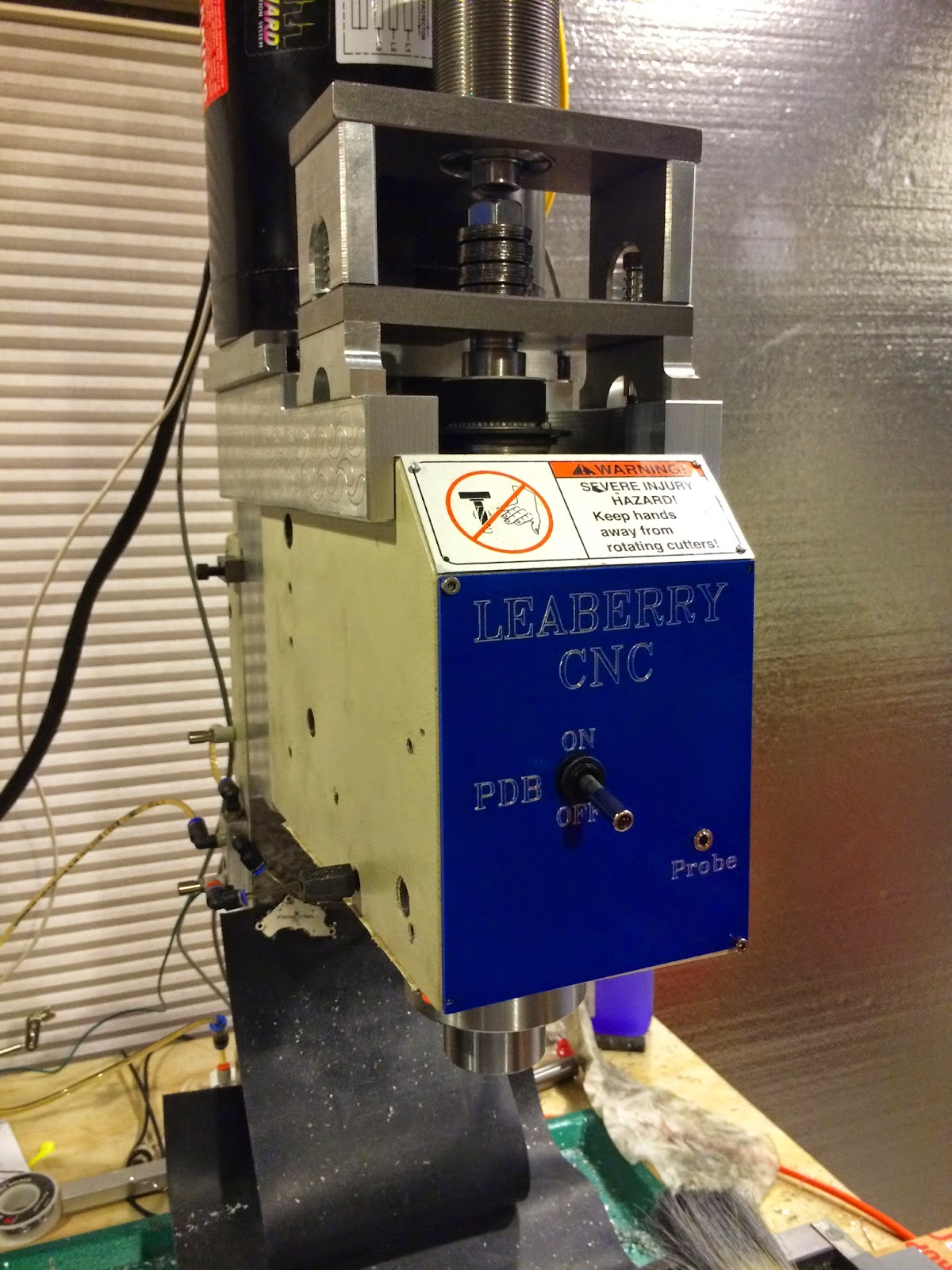
Belt Drive mounts, pulley bored out, tophat on

There are no bolts in the front belt drive mounts because I measured wrong and the holes are off a smidge


The fancy engraving on the side is because I bought a diamond drag engraver and of course you have to use it once you have it.

The belt drive conversion works great. I'm very happy with the performance of the VFD and motor. My z axis moves up and down just as fast as before and machining aluminum at 6k rpm is much better.

Electronics

I originally bought the Leadshine MX3660 which is an integrated 3 axis digital stepper driver and breakout board. It worked well for the first part of the build but has no provisions for an encoder. I didn't understand at the time but you don't need a breakout board. All you need is a Mesa 5i25 (or 6i25 if you have pci-e slots) and a 7i76. Mesa sells this combo for $200 and I recommend you just start with that. I swapped out the MX3660 for the Mesa 5i25/7i76 combo and bought Leadshine DM556 (x/y) and AM882 stepper drivers off ebay. I'm not sure if it was the Mesa hardware or the stepper drivers but the mill ran incredibly smooth after the upgrade. With the MX3660 the motors would whine a little while idle and my rapids were half the speed I expected them to be.

For stepper motors I bought a Keling KL34H295-43-8A Nema 34 906oz motor for the z axis and two Keling KL23H2100-50-4B Nema 23 570oz motors for the x/y axes. These are very powerful and have worked great. I run them all at 48V with a 12amp power supply I bought off ebay.

You need a functioning e-stop button. I bought one off ebay. I also bought proximity limit switches, a number of toggle switches, momentary switches, relays, Solid State Relays, and lots of 3,4,5 pin 16mm panel mount XLR connectors. I bought most of these electronics off ebay. The shipping from China is actually quite fast.

I used the XLR connectors to make a panel on the electronics enclosure. That way the cables go from the panel to the electronics and it's easy to unplug and replace/move components. Soldering all the XLR connectors was a lot of work but I still feel some sort of panel based system is needed. I also used a lot of 18/4, 18/2, 22/4 shielded security wire from Home Depot to wire everything up.

For rigid tapping you need a quadrature encoder and an index pulse. The encoder can be scaled, the index pulse must match the spindle rotation. In my case with a 1:2 pulley ratio (one motor turn, two spindle turns) I found it easiest to mount the encoder on the back of the motor and a separate index sensor on the spindle. The index sensor is a simple slotted photo interrupter. I used the original g0704 speed sensor and filled in all the holes except one. That provides a nice index pulse.

Rigid tapping was hard to wrap my head around but it's actually very simple in Linuxcnc. They slave the z axis travel to the spindle rotation. Instead of trying to force the spindle to go a very precise speed while the z axis is descending the linuxcnc control will adjust the z axis speed to match the spindle rotation. It uses the quadrature encoder for this matching and the index pulse is used so you enter the hole at the exact same spot every time. I rigid tap all the time at 1500rpm with no issues.

I chose to run all my electronics at 12v because I have the mini-itx computer in the same enclosure as the mill hardware so a 12v tap off the power supply was easiest. You should run 12v or 24v. 12v led switches are much easier to find and was a large factor in my choice. I like the lit switches so you know at a glance whether something is on or not.


Introduction

Like many others I became interested in CNC machining and decided to purchase a Grizzly G0704 benchtop mill and convert it to CNC. I purchased a copy of Hoss's Plans, the machine and went to work. I had basic hand tools, a cheap small drill press and no knowledge of machining.

7 months later and $8000 lighter I'm basically finished and while a lot of the conversion is pretty standard there are some things I did differently from most that I haven't seen documented anywhere before. I figure someone down the road will be grateful for the documentation and tips and tricks.

If you have the same dream I did, to have a metal cutting robot in your basement, but have no machining experience the only advice I can give is it's possible. You will crash tools, your vise will get dinged, it's all part of the learning process. Try to buy the cheap tooling first so when you destroy it and buy nice tooling it will stay nice.