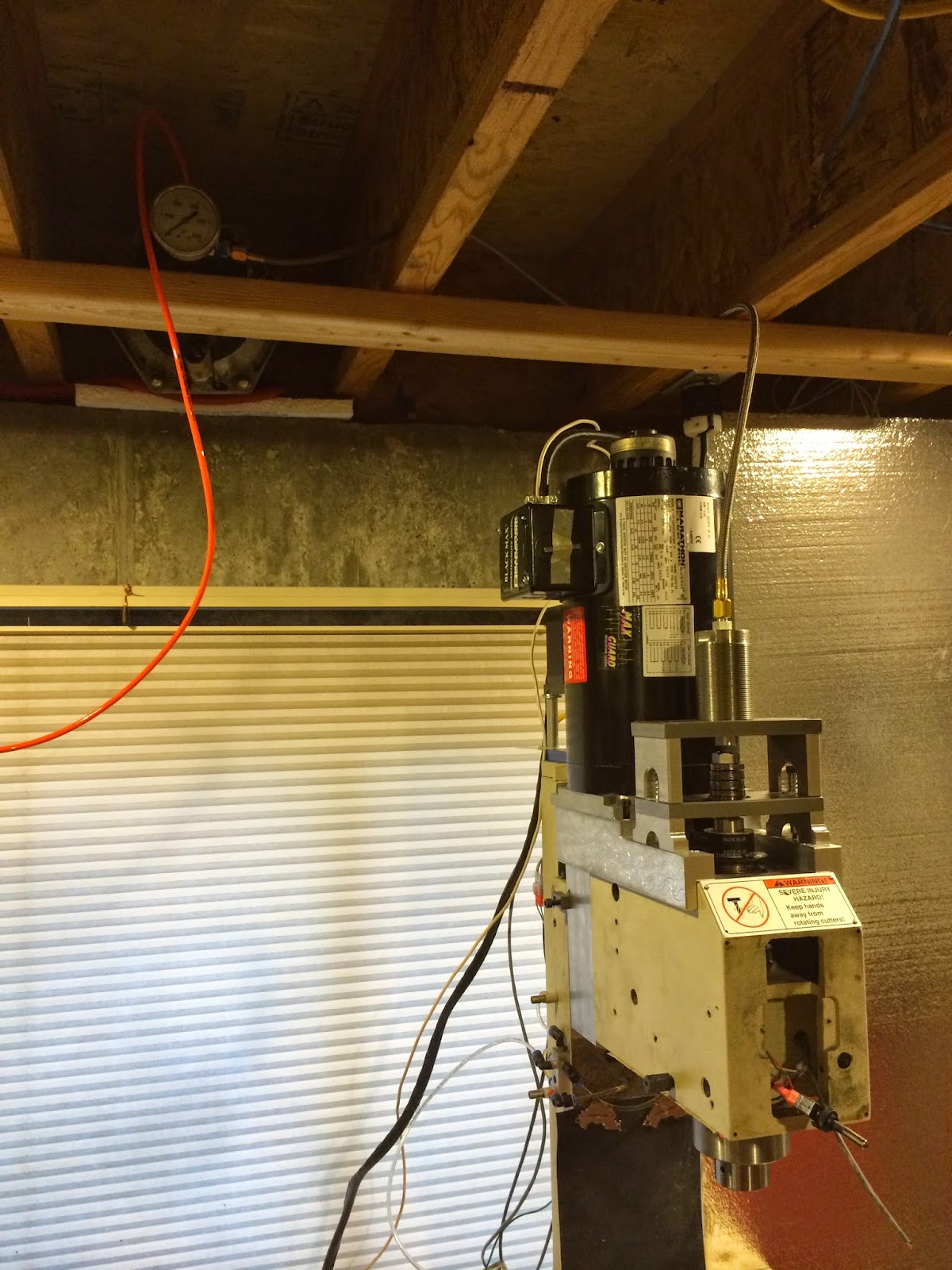
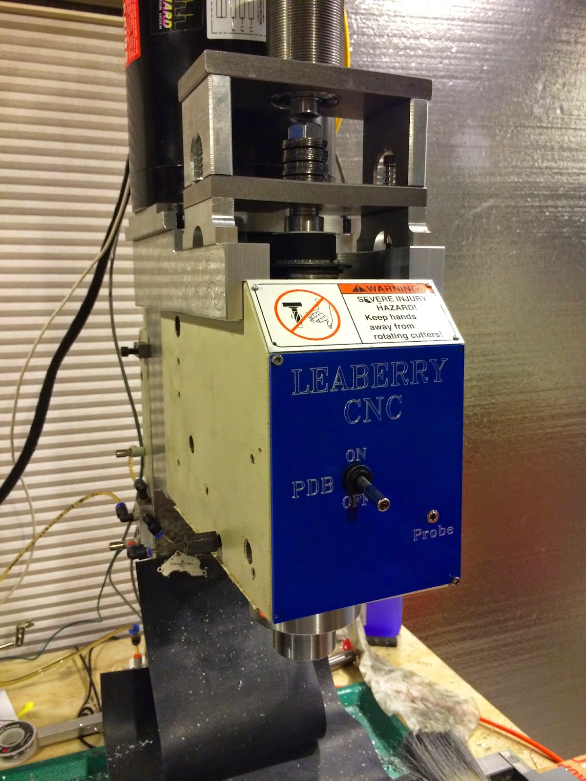
I decided to go with air over hydraulic. I looked at building my own air over hydraulic booster but it was much easier to buy one off ebay. I got an Enerpac B3006 booster along with a CST-40251 threaded hydraulic cylinder. The cylinder is about 2 inches wide and the exterior body is threaded 1.875-16 UNC. All you have to do is make a giant threaded hole in your PDB mounting bracket and it fits great. This is a great opportunity to do thread milling with a single point tool on your mill if you haven't already.
I was concerned about TTS tool pullout and with the B3006 booster I can produce about 3000psi in the hydraulic fluid. The CST-40251 cylinder has a surface area of 1.76 square inches so I can produce about 5200 lbs of force. The standard 4" 3 stage pneumatic cylinders produce about 3600 lbs. Tormach recommends 2500lbs of force on the drawbar to keep tools from pulling out.
The first time I activated the PDB I forgot about the 1.76 multiplier and actually bent the steel lifting plate with 4000 lbs of force. I plan on reinforcing the lifting plate and top plate by adding a vertical support that spans to front (ie a load bearing beam). It will be held on with two bolts so you can remove it and tighten or loosen the drawbar nut.
I did change the plans for the PDB slightly. I had to make it wider so it would fit my wider motor mounts and made more room between the lifting plate and the top plate. That extra room allows me to add more bellville washers for more force.
I would like to release the hydraulic PDB plans on Grabcad but since they were originally Hoss's design I'll need to ask him first. If you have the original Hoss plans and my Grabcad model of the 56c motor mount It will be pretty obvious how to make it slightly wider and taller to fit your situation.
 |
| Lifting plate. I made the slot slightly wider |
 |
| Lifting plate with legs on base |
 |
| Testing single point threadmilling for cylinder fit |
 |
| Completed Hydraulic PDB |
 |
| Completed PDB on mill |
 |
| You can see the Enerpac B3006 in the rafters on the left |
If you make a PDB you absolutely need a lockout on it so you don't activate it while the spindle is running. I know, you're the careful type who would never do that, but things happen and you will destroy your mill if the PDB activates while the spindle is going 5k rpm. Good news is, it's pretty easy to do. The concept is to take some output from the VFD that triggers when it's at zero speed and using a relay tie that to the PDB activation switch.
In my setup I use a 24v SPDT relay to take terminal B3 from my VFD and use that to determine whether the 12v+ line on the PDB switch should have power. If the terminal is high (ie spindle is stopped) then the PDB switch has power and can work. If the terminal is low, power is cut to the switch and you can flip it all you want and nothing will happen.
 |
| 24v relay documentation |
I have the switch for the PDB mounted on my mill head. If you wanted it to be controlled from LinuxCNC it would be very simple. Someday I might build an automatic tool changer and then I would need the PDB to be operated by LinuxCNC.


